Raspberry - Adding 433 to your Raspberry Pi
Thanks to: Justin Clayden
In this blog post I'll show you how to add RF 433MHz to your Raspberry Pi.
Requirements
- A Raspberry Pi (ORLY?) I'm using the revision 2 Pi, but if you have the revision 1 board, you'll just need to be mindful of the different pin numbers. As you'll see, the code uses *wiringPi* numbers and these haven't changed between revisions (thankfully!) but be aware that the RF receive pin we use will be BCM GPIO pin 27 in revision 2, and 21 in revision 1. That little tidbit is just for the curious; as I say the wiringPi pin numbering system abstracts this for us nicely.
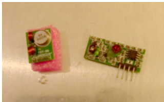
- A 433MHz Transmitter module
- A 433MHz Receiver module
- The code! https://github.com/ninjablocks/433Utils
Phase One - Install the Hardware

Step One - Install the Transmitter module
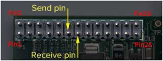
The requirements for this module are easily satisfied. Provide it with power and a data signal, and optionally an aerial, and it's well happy. We'll connect the DATA pin of this module to wiringPi pin 0. (This is GPIO pin 0 and BCM GPIO pin 17).
That's the 6th pin from the left on the lower row:

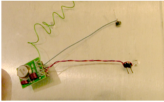
I used wire-wrapping techniques to connect mine:

Step Two - Install the Receiver Module
The requirements for this module are the same as for the transmitter, however there are some pin differences, so don't be caught out by this. The two middlemost pins are both data pins, and there is an entirely different area on the board to which to attach an aerial. Your receiver board may look different to mine. In fact my receiver has 8 pins.
The main message is to check your pin out documentation for your devices!
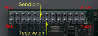
Attach the DATA pin of your receiver to wiringPi pin 2 - that's GPIO2; the 7th pin from the left on the lower row:

Phase Two - Run the Software
Step One - Clone/Download the '433Utils' github repo if you haven't already.
You'll find a 'RPi_utils' directory; that's where the code for this How-To resides.
Step Two - Build the Software
cd into the 433Utils/RPi_utils directory and do a:
make all
Run the codesend Sketch
On your Ninja Dashboard, choose the 'Listen' function. Then do a:
sudo ./codesend 12345
Almost any number will do here. You should see its hexidecimal equivalent appear in the Listen window. Change the number and verify that a different number appears in the Listen window.
Step Three - Run the RFSniffer Sketch
Within the 433Utils/RPi_utils directory, do a:
sudo ./RFSniffer
Grab your wireless button (or any 433MHz generating device.) and get pressing!
You should see its code appear in your terminal:
Starting Up..
Received 89745
Received 89745
Received 89745
Received 89745
Received 89745
NOTE: Your code may differ, of course.
Improvements
One limitation of this code is that it requires sudo to work, due to its calling of certain wiringPi functions.


0 comentarios:
Post a Comment