XMEN BLOGGER

Tuesday, January 03, 2017

Photography - Northern Lights


From: http://www.davemorrowphotography.com/2014/10/how-to-photograph-northern-lights.html
& http://fullsuitcase.com/photograph-northern-lights-beginners/


Preset Your Focus Point During the Day

It’s much easier to focus during the day than at night, for both you and your camera’s autofocus software.

Since focusing is one of the hardest parts of night / low light photography, getting this step out of the way during the daytime is always best practice.

Follow these easy steps to get started:

1. Set up your camera during the day with the lens you will be using to take your night / low light photos. You can do this at your house, or anywhere else that’s easy, it doesn’t have to be at the location where you plan on taking your night photos.

2. Adjust your lens to focus at infinity, or at a far away horizon. I always like to use my camera’s Live View Mode, zoomed in, and focus on the furthest horizon in my composition. This will ensure that you’ve focused at infinity. You can also focus by looking through your camera’s view finder. This works very well too.

3. Next manually make the final adjustments if / as required using the focus ring. I find that Auto Focus usually does very well during the day, but sometimes needs manual input to nail down the final focus in low light.

4. Take some more practice shots at an aperture of f/8 – f/11 and make sure the entire photo is in focus. If it isn’t focused, repeat Step 2 and Step 3.

5. Now your lens is focused at infinity.

6. Using a permanent marker, mark both the focus ring, and the barrel of the lens (non-rotating part of lens). Tape works as well, but may fall off over time.

This is a reference point that you will be able to use when returning to shoot at night or in low light. I’ve personally marked my lens using a silver Sharpie, allowing me to see the mark at night without using a headlamp or light.


1. Set your camera focus to infinity
Setting focus is probably the most challenging step of night photography, since your camera will not focus well in the dark. If you don’t do this right, you won’t get sharp pictures.
How to set your camera to focus to infinity? In human language, it’s basically making sure that your pictures are sharp at the far horizon. It’s best to do this during the day. Select manual mode on your lens, focus to infinity, adjust as needed and mark your lens at the right place. You can use permanent marker, silver sharpie or tape for it. When you’re outside at night, all you need to do is set your lens to the right position.
If you couldn’t do this during the day, try looking for a brighter point (a house or a lit road in the distance) in the area you are and focus your camera sharp on it. In the worst case, you might try using your flash light to illuminate the point as far from you as possible and focus on it. Make sure you don’t turn the lens after doing this, reframe for the Northern Lights and shoot.

2. Metering mode
Use the following metering mode for Northern Lights photography: Evaluative Metering for Canon cameras or Matrix metering for Nikon.


3. Wide aperture
Set your camera to Manual Mode for Northern Lights photography (M on most cameras) and make sure you set the aperture as wide as possible. So at 2.8 if you have a f2.8 lens or at f4 if you have a f4 lens.

4. Exposure time
If aurora moves slowly, try a 12-20 second exposure. For very vague auroras you might even need 20-25 seconds. If aurora moves fast, however, 5-10 seconds might be more than enough.


5. What ISO value to use to photograph auroras
Depending on how bright auroras are, you might need to adjust your camera’s ISO settings. Remember: the higher the ISO, the bigger chance of ‘grain’ in your picture. Try shooting at ISO 800 if auroras are very bright. You may need to increase ISO to 1,600-3,200 or even more if it’s really dark.

6. Best white balance settings for Northern Lights photography
You’re probably not shooting in RAW as a beginner (neither do I, to tell you the truth), so you want to get the colours as close to reality as possible straight from the camera. You can use Automatic white balance mode and see what it gives. I found that setting white balance to Custom mode and choosing Kelvin values of 2,800-4,000 worked best for me. Or shooting in RAW mode!!!


1. Start out shooting with an ISO of 400-800 and take a practice shot.

2. After doing so, if your practice shot wasn’t bright enough, increase your ISO to approximately 1200 and take a practice shot.

3. If the photo still isn’t bright enough, continue to increase your ISO until it is. I usually shoot in the ISO range of 800-4000.


Check histogram, and decide...

Camera Settings: 10 Seconds, f/2.8, ISO2500 - Overexposure
Camera Settings: 10 Seconds, f/2.8, ISO2000 - Correct Exposure
Camera Settings: 10 Seconds, f/2.8, ISO1000 - Optimal Exposure


Fast guide!!!

1. Find your location and composition first. Even at night the story in the image matters, and you want foreground, middle ground and background whenever possible.

2. Set your camera on manual focus and choose the manual setting (M) from your camera menu. Then choose the aperture setting and open the lenses as far as it will go, dialing in lowest aperture F-setting available.

3. Set the self-timer - to avoid camera shake from pressing the shutter - and choose an ISO around 800-1600.

4. Look at your LCD display (turn it on if needed) and zoom in as far as it will go and use menu controls to move the zoomed view to an area in the sky with extra bright stars.

5. Turn the focus ring on your lens to infinity. It is the little symbol that looks like a horizontal eight, and you will notice the stars more and more becoming small piercing dots. Fine-tune, using miniscule movements, until you have gained the sharpest focus possible,

6. Now that the stars are in focus the northern lights will also be, and you are ready to start shooting. Choose a shutter speed around 5-8 seconds initially and check the first results.

7. Adjust the exposure using only shutter speed and ISO, keeping the aperture fixed and the focus unchanged, and keep shooting the northern lights as they change in the sky.


ESP8266 ESP-01 Firmware Update with Arduino


From: http://www.elec-cafe.com/esp8266-esp-01-firmware-update/


pdate ESP8266 ESP-01 to new firmware for my home automation project, initially the module was working perfect to you.

Step 1: Parts List

Arduino UNO
ESP8266 ESP-01

Step 2: Download ESP8266 Flasher and ESP8266 Firmware

Download ESP8266 flasher from this link
ESP8266_Flasher

Download ESP8266 Firmware from this link
AI-v0.9.5.0 AT Firmware.bin

Step 3: Connecting ESP8266 to Flash mode

ESP8266 <-> Arduino UNO


Tx    <->Tx (D1)
Rx    <-> Rx (D0)
VCC   <-> 3.3v
GND   <-> GND
CH_PD <-> 3.3v
GPIO0 <-> GND (Connect into flashing mode, disconnect after finish)

** Connect ESP8266 RX to Arduino UNO Rx and ESP8266 TX to Arduino UNO TX **

Step 4: ESP8266 to Boot Mode

Upload Blink example code to Arduino UNO

// the setup function runs once when you press reset or power the board
void setup() {
// initialize digital pin 13 as an output.
pinMode(13, OUTPUT);
}

// the loop function runs over and over again forever
void loop() {
digitalWrite(13, HIGH); // turn the LED on (HIGH is the voltage level)
delay(1000); // wait for a second
digitalWrite(13, LOW); // turn the LED off by making the voltage LOW
delay(1000); // wait for a second
}

** if you can’t run upload , please remove TX and RX and then connect after finish **

Step 5: Uploading Firmware

Browse the bin file or firmware version files
Set you COM Port –> (view Device Manager> Ports(COM&LPT))

Click Download button


Complete update firmware

** In the end at 99% it will show some error but this is ok.


Test AT commands in Arduino Serial Monitor
Set Both NL & CR
Set Baudrate at 9600
Enter “AT” and you will get “OK”.
Enter “AT+GMR” and check the firmware version.

ESP8266 ESP-12 Standalone with Blynk


From: http://www.instructables.com/id/ESP8266-ESP-12Standalone-Blynk-101/step4/Results/


Hardware:

1. ESP8266 board
2. USB-TTL/FDTI adapter 3.3V
2. Smartphone (IOS/Android)
3. Dupont wires
4. LED
5. Breadboard
6. Power Source 3.3V.. Note: separate power source required for ESP board

Nikon D7000 - ESP8266 + Smartphone Wireless Remote for DSLR with (possible) GPS


FROM: Instructables!!!!
http://www.instructables.com/id/ESP8266Smartphone-Wireless-Remote-for-DSLR-with-po/step4/The-Sketch/
& http://statusorel.ru/technology/esp8266-smartphone-wireless-remote-for-dslr-with.html


All Items:

A while back I came across this awesome project by CosmicMac. Basically you can trigger your DSLR wirelessly using your smartphone via the ESP8266 connected to the DSLR. Given that not all cameras have support for built in shutter terminal, and that different brands have different pinouts for their camera, you need to modify the peripherals accordingly. My camera is a Nikon DSLR D3200 with remote terminal using proprietary MC-DC2 port. You can buy a cheap wired shutter remote online for around $1.

What’s interesting is that the MC-DC2 also has a pin for GPS data. After doing some research I found these projects:

1. Nikon D90 Homemade GPS

2. BUILD A BLUETOOTH GPS UNIT FOR NIKON CAMERAS

I was about to make my version of CosmicMac’s project using ESP-12 development board and programming using the Arduino IDE when I got the idea of trying to send GPS data from phone to ESP mcu and communicate it to DSLR. While in theory this sounds promising,I came into a lot of trouble mostly because:

1. I am a beginner.

2. The camera uses NMEA 0183 protocol to read GPS data while getting this form of data is tricky. It might be possible by writing a native android app using NMEA listener but I didn’t try it.

3. I wanted to use the Blynk app to implement the project, however direct communication with ESP and smartphone is not yet possible and GPS widget is not yet available. Maybe I will make it in the future :)

So, my project is mostly a spinoff of CosmicMac’s project with possible integration of Ido Nassimi and Grinkevich projects. I am also submitting this project for the REMIX 2.0 contest, so if you like it please vote.

Here are some of the major changes I made from original projects:

1. Using arduino to program ESP mcu instead of nodemcu firmware.

2. Using ESP-12 instead of ESP-1

3. Using HTML 5 geolocation API to get user’s data location

4. Setting up wifi web server on esp mcu to communicate with smartphone

5. I also implemented a FOCUS option since not everybody uses manual focus.

DISCLAIMER: This project is more of an experiment. Its main objective is to provide of proof of concept and may open the eyes of others to adapt it to their own imagination. As I stated, Im a beginner, so maybe there are codes that are written that may look crude and there are possibly better ways to implement them. I try to give credit to anyone whose code or ideas I used but however the list is unending ( i inserted links to relevant projects wherever possible). I apologise if I missed anyone. This project is also a learning process for me and any feedback is welcome. I had to research a lot about HTML and javascript. I am grateful to anyone who helped me write this project, albeit they might not be aware.

Also, about the GPS part, it’s still a work in progress so bare with me.

Step 1: Overview

Firstly, I’m going to introduce the materials needed for this project. Then dive into how to write the sketch to the board. I’m also going to explain key methods in the .ino sketch. Afterwards we look at the hardware setup. Then finally see it in action.

Step 2: Materials

1. ESP8266 microcontroller, I bought mine, ESP-12 development board, from TaoBao for around 3 dollars.

2. USB-TTL converter for writing sketch to ESP8266. I bought one with adjustable 3.3V and 5V logic. Be careful!! the esp uses 3.3V

3. 2* 4N25 optocouplers

4. 2 resistors

5. Jumper wires

6. Breadboard

7. Smartphone and DSLR, not accounted in bill of course

8. Corresponding shutter remote

Step 3: Setting up the Board

There are a lot of tutorials out there on how to setup the esp for arduino programming.

I made my first instructable mentioning that. Look at step one here.

We are using esp standalone, that is without AT firmware.

Set up hardware as shown in step 3 here

make sure you have separate power supply for esp, 3.3V!!!!!!

You might want to upload a simple sketch to make sure everything works fine.

Then download this sketch and upload to board.

Step 4: The Sketch

Initially, we define libraries used and pins.

Change the FOCUS and FIRE pin numbers as desired.

Then change your preferred “ssid” and “password” for the Access Point setup. Note, this is not the ssid or password of you home network. It is used on smartphone to connect to ESP.

The /* Set page handler functions */

This part is based on Ashish Derhgawen’s sketch.

Here we setup the page links name and assign method names to handle them.

/* Root page for the webserver */

Where we setup how to handle the root. Basically the address you first go to to load the root page is the IP address provided in serial monitor. 192.168.4.1

The page contains links 3 options:

The remote with timer page

It contains code to display “/remote” page. On this page you can select timer, then press the submit button.

The values are sent to ESP where the delay is processed and then the FOCUS is triggered (also allows 5s for focus to complete) the FIRE is triggered to actually take the picture. you can modify the code according to your requirements.

The compatibility page

This page just checks if your smartphone browser supports geolocation. On prompt on smartphone, please allow access. Also, you may need to enable location services for browser in device settings.

The Remote+ GPS page

Here we first convert geotag values to NMEA and send a string to esp.

This part requires a lot of coding. The $GPRMC and $ GPGGA( please make sure you read NMEA protocol first) need to be sent to camera. This part is a bit experimental as the values need to be computed, a checksum calculated and sent as TTL logic, possibly 5V for some cameras.

Remote_GPS_separate_final_.ino

Step 5: Wiring

Show All Items

After writing the sketch to the mcu, we can finally run our code independently.

The wiring is similar to the one used in CosmicMac’s project. I modified it a little bit.

1. There are two output pins, thus 2 optocouplers, one for focus, one for shooting.

2. The MC-DC2 port I used for my project needs to be modified as only wires for ground, focus and shoot are wired inside . For those wanting to try the GPS, this modification is required, otherwise for the remote, the 3 wires are good.

I am not going to dwell too much on how to do this as these two places provide ample info

(i) https://grink.com/2010/12/05/nikon-d90-homemade-gp…
(ii) http://www.diyphotography.net/build-a-bluetooth-gp…

Step 6: The Web UI

Show All Items

After wiring and writing code to esp, it’s time to actually use the setup.

Connect your smartphone’s wifi to the name you set up as SSID for the access point.
Open your browser, and to go IP provided in serial monitor.

Choose your options for shooting

Step 7: The END

That’s it folks.
Thank you for your attention.

I welcome any feedback and help especially if someone wants to refine the codes or help with the GPS part.

Nikon D7000 - Clone Nikon ML-L3 IR Remote and Emulation


From: http://goughlui.com/2013/12/06/teardown-and-project-clone-nikon-ml-l3-ir-remote-and-emulation/


Teardown and Project: Clone Nikon ML-L3 IR Remote and Emulation

Users of Nikon cameras, including the D3200, have had several choices for remote triggering. The use of a wired remote is traditional, with infrared (IR) remotes being common accessories for many and Wi-Fi just becoming the latest craze.

The Product

The Nikon D3200 is compatible with the Nikon ML-L3 IR remote. A quick look on eBay reveals a large number of clone (compatible, non OEM) remotes available for as little as AU$1.20 posted. That includes the CR2025 battery as well. For that price, you’d be silly to go without one (or two, or three)!

I’m not sure what the original ML-L3 is made of, but this is very much like the cheap “flat” remotes provided with many TV tuners. It is constructed of a single PCB, using a single CR2025 coin battery. The buttons are made by carbon-coated dome-formed thick self-adhesive plastic sheet which sits over the PCB interlocking finger pattern traces. It’s not particularly glorious or durable with repeated use, but that’s the way things are.

Tearing it apart reveals an extremely simple construction. The PCB underside is marked with KD301B-A054-002 and FS3423. The plastic mold is marked with KD301B. The PCB utilizes a single IC, capacitor and IR LED. There are no resistors, or even ceramic oscillators (455khz commonly seen on IR remotes, as 455khz/12 = 37.91khz).

here’s no real information I can find on the IC, it’s marked PRT-P08 TX0917. This IC must be able to generate the IR code pattern (including the timing) and limit the current to the LED on the on-phase. I can’t say all clone remotes would use this chip – others may opt for chip-on-board construction.

Tracing the very-simple traces gives me the following schematic:


Simple ain’t it? You could probably alter the circuit board to generate the IR code on other triggers. I don’t know what the unconnected pins are used for – or if they are used at all. Maybe it’s programmable? Maybe there are other modes?

The remote itself fires off the D3200 very reliably, and it’s cheap. I can’t complain of the quality given the price, but I wouldn’t want to rely on having just one in an emergency. Infrared trigger isn’t as “reliable” as wired triggering, since you do need to have a working battery and be within range of the sensor. The sensor has to be activated through the menus, and the camera will time out and sleep the sensor if it’s not been used for a while, so the applications are limited. But it’s nice since it involves no touching the camera (after set-up) and no possibility of conducting any vibrations through trigger cables.

Analyzing the Code

It’s not the first time I’ve worked on emulating infrared remotes. I had posted two videos earlier, which are quite long which does show my previous work (although isn’t easy to follow from the video). I think it’s much more illustrative to write about it instead.

Incidentally, this remote proves to be one of the simplest to emulate.

The first thing you need to do is “record” the signal from the remote. You can do this directly by reading the voltage across the LED (which is most direct, and gives you the raw data including the carrier frequency of the IR system). Another way is to use an IR receiver like the ones used in TV tuners and probe with TTL output (high for presence of 38khz IR carrier, low for absence of 38khz IR carrier).

An IR receiver from a TV tuner.

The method with the IR receiver was used in my former emulation attempts, but it’s not ideal as the sensor may not be able to give you data for non-38khz IR systems. Most of them are 38khz, but there are some using other rates.

IR transmission mostly involves the keying on-and-off of a 38khz signal. The use of 38khz allows for the filtering of “steady” IR background and general noise.

It’s important to capture the IR pulse train using an oscilloscope, high rate data-logger or something similar. I used my Poscope basic2. I cannot recommend users to buy this product, as it only supports Windows, triggering has no hold-off options and is hit and miss, there’s no anti-aliasing filter, the software is pretty broken in Recorder mode when recording at high rates, the data is recorded in a format needing conversion by their tools and it is very limited in sampling rate. I have a heap of trouble with it in general under Windows 7, although older versions of software on Windows XP with specific USB controllers can work semi-reliably. But with enough patience, even something this basic like this is sufficient.

The first thing to understand is that IR remotes tend to send the same code over and over when the button is depressed. In this case, the remote actually sends its code three times over – here we can see just one iteration which takes about 100ms, which repeats.

Most of the time is with the IR LED off, the code itself is very simple. Re-acquiring zoomed in (noting polarity is due to the way the connections were made):

We can see the remote starts with a 2ms burst of 38khz, followed by 28ms rest, 0.5ms burst, 1.5ms rest, 0.5ms burst, 3.5ms rest, 0.5ms burst, 63.5ms rest. That is the IR code we need to emulate to make it “work”. Note that slight timing and frequency differences are expected – say different battery levels and component tolerances.

Take it from me, it’s 38khz – I looked closely into it.

Making it Work

The first thing you need to emulate something like this is a suitable IR LED. Instead of buying it off the shelf, I decided to pinch one from a “useless” remote I had from my RTL-SDR purchases. I’m never going to use the remote – so why waste the LED?

Having extracted the LED, I have to ensure its safety. The voltage drop of my IR LED is about 1v at 1mA, and using a 5v Arduino, I decided to go with two 680 ohm resistors in parallel for an LED current of about 12mA. LEDs like these may be capable of currents up to 20mA, but I decided to play it safe. In fact, it’ll be safe to overdrive it slightly given the low duty cycle of the remote signal.

Of course, as a lazy person, I decided to solder it to some header pins air-wire style, and then cover it with globs of hot glue.

Positive in this case is the pin on the left. I decided to plug it straight into my Arduino Mega 2560 (clone) which I had handy, but you don’t need something this powerful.

The first thing is to write the code that approximates the timing. You’ll find that you will encounter some possible issues say if you use tone() with duration, so instead, use tone() and noTone() instead.

Here is the code – I tested my code, and it does fire off my D3200:

// Nikon Remote Emulator by Gough Lui (http://goughlui.com)
// A1 = IR +
// A0 = IR -

int count=0;

void setup() {
pinMode(A0,OUTPUT);
digitalWrite(A0,LOW);
pinMode(A1,OUTPUT);
digitalWrite(A1,LOW);
}

void loop() {
// Send code three times, as the clone remote does
// Delays are tuned to account for overhead of library code.
while(count<3) {
tone(A1,38000);
delay(2);
noTone(A1);
delay(28);
tone(A1,38000);
delayMicroseconds(200);
noTone(A1);
delayMicroseconds(1500);
tone(A1,38000);
delayMicroseconds(200);
noTone(A1);
delayMicroseconds(3300);
tone(A1,38000);
delayMicroseconds(200);
noTone(A1);
delayMicroseconds(100);
delay(63);
count++;
}
}

Note that the delay timings are not as suggested by the scope capture – this is because there is overhead in the Arduino library functions which take time to execute. Instead, the times are trimmed through trial and error to result in a trace on the scope which closely mirrors the original (although slight timing deviations would be okay). You don’t need to match the original quite 100% as each remote may have slight component differences resulting in offset carrier frequencies and timing. As long as you’re within a few percent, the device should recognize the transmitted code.

The pulse train, as measured by my crappy PoScope basic2 unit looks pretty damn close to the original remote – so now I’ve got the code to trigger my camera using IR. What to do now? Well, you could make some specialized trigger system algorithmically controlled by the Arduino … it’s really up to your imagination.

Besides, now you know what to do when you want to emulate a remote :).

Nikon D7000 - Add a GPS


From: https://www.cyrozap.com/2011/08/13/diy-nikon-d5100-gps/


You need:

- Microsoft GPS-500 (or GPS-360, it has the same pinout). You can get one on eBay for $20 (and if you're lucky enought, it came with a TTL-USB cable AND Streets & Trips 2008 AND an MSN Direct Receiver).
- Shutter connecting cord for Nikon D5100 (or D7000 ;-P). They use MC-DC2 connector (mini-USB propietary connector)
- Ethernet cable that you're willing to strip (if you want, or the same Pharos GPS cable-connector).
- Kapton tape (if you want).
- 5v diode.
- Some sort of strain relief for the wires at the camera connector.
- A steady hand.

I got the pinout data for the GPS from here and the pinout data for the camera connector (with a lot of other useful info) here. Note: on the Flickr photo, read my comment for clarifying info and corrections.


My setup doesn't use any TTL voltage converters because the D5100 seems to be able to use the 3.3V TTL from the GPS. I may include a diode in the power line at some point to drop the voltage a little because the camera is feeding 6V to the GPS and its specs say it has a max power input of 5.5V, but it's working so far.

Basically, connect pin 5 on the GPS (the one to the right of the leftmost one when the gold contacts are facing up) to the power pin on the camera connector, pin 2 on the GPS to ground on the camera connector, and pin 3 on the GPS to TTL/Serial in on the camera connector.

  GPS PIN2 - MC-DC2 PIN3 - GND
  GPS PIN3 - MC-DC2 PIN7 - DATA (4800 TTL NMEA)
  GPS PIN5 - MC-DC2 PIN4 - +5v

EDIT: I added the diode; it dropped the voltage to about 5.0V-5.2V. I feel a bit better now.

Oh, by the way, don't connect Pin 1 (GPS Rx) to ground! I happened to do this by accident and it screwed up the serial output until I fixed the solder bridge.

This setup may work for other newish Nikon cameras, but they may not be 3.3V TTL tolerant, so YMMV.


Pharos GPS-500 & GPS-360 specs


Wednesday, December 28, 2016

Raspberry Pi - Install Node.js on Raspberry Pi 2 Model B


$ wget https://nodejs.org/dist/v7.3.0/node-v7.3.0-linux-armv7l.tar.gz
$ tar -xvf node-v4.0.0-linux-armv7l.tar.gz
$ cd node-v4.0.0-linux-armv7l

$ sudo cp -R * /usr/local/

$ node -v


FROM: http://thisdavej.com/beginners-guide-to-installing-node-js-on-a-raspberry-pi/

$ curl -sL https://deb.nodesource.com/setup_7.x | sudo -E bash -

$ sudo apt install nodejs

$ node -v
v7.3.0
$ node
> 1 + 3
4
> # We can hit Ctrl-C twice to exit the REPL and get back to the bash (shell) prompt.

Tuesday, December 27, 2016

Raspberry Pi - Node Telescope Server for Stellarium/SkySafary 4


From:
 https://www.npmjs.com/package/node-telescope-server
 https://github.com/fcsonline/node-telescope-server

 http://blog.raceconditions.net/wifi-telescope-control-with-skysafari-4/
 https://www.npmjs.com/package/stellar-socks


Overview
This is a small tutorial to connect Stellarium with a Celestron telescope, and control it remotly. The next diagram describes all the required elements to build your own homemade planetarium.

Requirements
 - RaspberryPi with raspbian installed.
 - A Ethernet wire or a Wireless adapter for your Raspberry Pi (I prefer a Wireless LAN adapter).
 - Telescope Celestron (Nexstar Protocol) with GoTo feature (Celestron NexStar 127SLT, in my case).
 - USB to Serial port adaptor (recommended).
 - A computer with Stellarium installed.

Installation
The first step is to install the nodejs and npm packages:

pi@raspberry $ sudo apt-get install nodejs npm

Verify that the current nodejs and npm packages have compatible versions:

pi@raspberry $ node -v
0.8.9

pi@raspberry $ npm -v
1.1.4

If the previous commands have returned older versions you should install node and npm manualy:

pi@raspberry $ wget http://www.nodejs.org/...
pi@raspberry $ tar zxf node-0.8.9.tar.gz
pi@raspberry $ cd node-0.8.9
pi@raspberry $ ./configure && make
pi@raspberry $ sudo make install

pi@raspberry $ node -v
0.8.9
pi@raspberry $ npm -v
1.1.4

Then install the node-telescope-server module in your Raspberry running:

pi@raspberry $ sudo npm install node-telescope-server -g

Now, connect your USB to Serial port adaptor to one of your available ports in the Raspberry Pi and connect the other side to the telescope. Run the next lsusb command to identify the USB device to be initialized:

pi@raspberry $ lsusb
...
Bus 001 Device 002: ID 4358:2523
...
pi@raspberry $ sudo modprobe usbserial vendor=0x4358 product=0x2523

Run dmesg command and you shall see lines like these:

pi@raspberry $ dmesg
usbserial_generic 1-1:1.0: generic converter detected
usb 1-1: generic converter now attached to ttyUSB0
usbcore: registered new interface driver usbserial_generic

Identify the device uid assigned by the kernel to the serial port, aka ttyUSB0

Start a nts instance to control your telescope. You should specify -t and -i arguments with your telescope type and file to the device file descriptor:

pi@raspberry $ nts -s stellarium -p 5050 -t nexstar -i /dev/ttyS0
Remote stellarium control server running at port 5000 to a nextar telescope
This command starts a Stellarium control server listenning at port 5050 connected to a Nexstar (Celestron telescopes) sending commands to /dev/ttyS0 device.

Now the Node Telescope Server (nts) is ready to receive instructions to move your telescope to the desired target.

Next step is to connect this nts instance with the Stellarium software. Open Stellarium and press Ctrl+0 or go to the telescopes window. Add a new telescope and choose the External software or remote computer. Then choose a desired name for your telescope, for example "NodeJS-RaspberryPI". Then specify the ip assigned to the RaspberryPI and the port listening by nts instance, in my case 192.168.5.1 and 5050 (because my Raspberry is configured as a AP gateway). Save the telescope configuration.

Multiple servers

$ nts -c config.json
Telescope Dummy: Remote dummy control server running at port 4000 to a dummy telescope
Telescope Stellarium Dummy: Remote stellarium control server running at port 4001 to a dummy telescope
Telescope Nexstar: Remote stellarium control server running at port 5000 to a nexstar telescope
Disabled remote web control server running at port 5001 to a nextar telescope

This command starts several servers defined in the config.json file.

An example of config file:

[
{
"name": "Telescope Dummy"
, "server": "dummy"
, "port": 4000
, "telescope-device": "/dev/null"
, "telescope-type": "dummy"
},
{
"name": "Telescope Stellarium Dummy"
, "server": "stellarium"
, "port": 4001
, "telescope-device": "/dev/random"
, "telescope-type": "dummy"

, "enabled": true
},
{
"name": "Telescope Nexstar"
, "server": "stellarium"
, "port": 5000
, "telescope-device": "/dev/ttyS0"
, "telescope-type": "nextar"
, "camera-device": "/dev/null"
},
{
"name": "Telescope Lx2000"
, "server": "web"
, "port": 5001
, "telescope-device": "/dev/ttyS0"
, "telescope-type": "lx2000"
, "camera-device": "/dev/null"

, "enabled": false
}
]

Last step is to click on connect button and the status label should change to "Connected".

Finally you have the Stellarium connected to your telescope! Choose the desired object and pres the Ctrl+1 and realize that the telescope start pointing to the target. :-)

Enjoy it!


-Do the same but now with Stellar-Socks (a TCP server for interacting with a telescope via serial connection from planetarium software such as Stellarium and SkySafari).

$ npm install stellar-socks

Configuration
By default the server will open a TCP socket on port 5000, and connect to a telescope on /dev/ttyUSB0. To configure these values, change the configuration in config.json.

Starting the Server

Before you start the server, you'll want to make sure you have your telescope on and aligned, as well as the Raspberry Pi (or other device) connected to the serial port on the telescope. You'll also want to make sure you have the configuration file config.json set up properly for your environment.
To start the server, navigate to the installation directory from the installation step, and run the following command:

$ npm start

When you run the command, the service will start up and announce its status as shown in the image below.

Running StellarSocks

You are now ready to configure your remote planetarium software to connect to the server.

http://www.nexstarsite.com/PCControl/RS232Cable.htm

Raspberry Pi - Reset user "pi" passwd


To reset your 'pi' password:

Power down and pull the SD card out from your Pi and put it into your computer.

Open the file 'cmdline.txt' and add 'init=/bin/sh' to the end. This will cause the machine to boot to single user mode.

Put the SD card back in the Pi and boot.

When the prompt comes up, type 'su' to log in as root (no password needed).

su

Type "passwd pi" and then follow the prompts to enter a new password.

passwd pi

Shut the machine down, then pull the card again and put the cmdline.txt file back the way it was by removing the 'init=/bin/sh' bit.

init=/bin/sh

Friday, December 23, 2016

Raspberry Pi - Blind (sunshades) control


WiringPi

Software

There ar three pieces of software (wiringPi (from Gordon Henderson), shell script, RaZ-OR function) to be installed, from which the last is optional for use by people that do have the RaZberry plugged in.

WiringPi module

The GPIO pins can be controlled directly from the command prompt. For security reasons that function does require access as root. That is not always convenient. Therefore the WiringPi module should be installed(following Plan B) on the Raspberry. It not only deals with the "root" problem, but it also makes interfacing easier.

$ gpio readall


For this example we use "soft" pin numbers 12,13,14 in the first column named wPi. Those correspond to the physical pin numbers 19,21,23 as you can see in the above table, which was made using the gpio readall command. Check this for your Pi board.

Raspberry Pi pins:

PIN 01 - 3v3 battery (+)
PIN 19 (GPIO12) - down button (+)
PIN 21 (GPIO13) - stop button (+)
PIN 23 (GPIO14) - up button (+)
PIN 25 - ground (-)

Shell script

If you run OpenRemote on the Raspberry Pi, the sunshades can be controlled via the OpenRemote Shell execution protocol with the following script:

#!/bin/sh
PIN=$1
/usr/local/bin/gpio mode $PIN out
/usr/local/bin/gpio write $PIN 1
sleep 0.1
/usr/local/bin/gpio write $PIN 0

If you run on RaspCLI:

/usr/local/bin/gpio mode 19 out
/usr/local/bin/gpio write 19 1

Result is:


If you do not run OpenRemote on the Raspberry, you can control the shades using this script via the RaZ-OR module (see below)

For the further description it is assumed the file is called GPIO.sh. It is called with a single numerical parameter that is interpreted as follows if you use the above wiring diagram and the wiringPi module:

down  : 12
stop  : 13
up    : 14

Then:
/usr/local/bin/gpio mode 14 out
/usr/local/bin/gpio write 14 1
-> Goes up

And:
/usr/local/bin/gpio mode 13 out
/usr/local/bin/gpio write 13 1
-> Goes stop

The script makes the GPIO temporarily go high, which makes the Somfy remote button close for a short while.
In this script the wiringPi PIN numbers are used. See more detail on those pin assignments here.


REFERENCE

Somfy control
http://www.openremote.org/display/docs/OpenRemote+2.0+How+To+-+Control+Sunshades+-+Somfy+with+Raspberry+Pi

blind-control
http://romor.github.io/blind-control/

Raspberry Pi - WiringPi with RF 433mHz transmitter


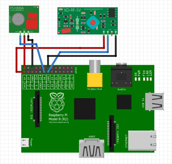
WiringPi GPIO pins


Pin 2 - Vcc (5V)
Pin 6 - GND
Pin 11 - GPIO 17 - (WiringPi Pin 0): Linked to Emitter
Pin 13 - GPIO 27 - (WiringPi Pin 2): Linked to Receiver (RF433MHz – XY-MK-5V)


FROM: http://i-build-stuff.blogspot.com.es/2015/01/wireless-room-temperature-monitoring_27.html

With that simple setup on i can go ahead i can try and send data and see if it is being received.

Now on my computer i connect to my Raspberry Pi using ssh

Code 1 : ssh pi@yourlocalIPaddress
(once prompted, enter your password. Default is "raspberry")

Then I have to go to the specific folder where the 433Utils programs are stored in order to start them.

Code 2 : cd 433Utils/RPi_utils

This bring you to the correct folder where the sending program and the sniffing program are stored.
Now i open another Terminal window and login via ssh (code 1) and i go to the 433Utils folder (code 2)

In the first terminal window start the Sniffer program.

Code 3 : sudo ./RFSniffer

Now in the second terminal window send a code

Code 4 : sudo ./codesend 121234 (any random integer)

If everything works fine, you should see your integer going through the Sniffer result window just like in the below screenshot :

pi@raspberrypi ~/wiringPi $ gpio readall


(*) Raspberry Pi RF remote (433MHz)

FROM: http://npham.dk/?p=34

Creating RF transmitter / receiver

Source: http://shop.ninjablocks.com/blogs/how-to/7506204-adding-433-to-your-raspberry-pi

I bought my RF transmitter and receiver from eBay a about 1$.
Connecting RF transmitter and receiver to the Raspberry Pi is pretty simple.
Both the reciver and transmitter has a VCC, GND and DATA pins.
And all you do is connect it to the Raspberry Pi GPIO pins.


Install RPi_utils

Source:
https://github.com/ninjablocks/433Utils/tree/master/RPi_utils

Start by installing RPI_utils

sudo apt-get update

#Installs GIT
sudo apt-get install git
sudo apt-get install git-core

#Installs 433utils
git clone git://github.com/ninjablocks/433Utils.git
cd 433Utils/RPi_utils/

#Installs wiringPI
git clone git://git.drogon.net/wiringPi
cd wiringPi
git pull origin
./build

#Builds RPI_util
cd ..
make all

Testing and decoding RF signal

To capture and decode the RF signal from the remote, I ran the program RFSniffer.

sudo ./RFSniffer

When I push the A (on) button on the remote, I get the following code on the screen.

Received 5260625
Received 5260625
Received 5260625
Received 5260625
Received 5260625

To test if the transmitter works you can send the received value with this command.

sudo ./codesend 5260625

If you convert 5260625 to binary, you get 10100000100010101010001.
And looking at the binary value of all the buttons, you start to see a pattern.

Button Decimal value Binary value
A (On) 5260625 10100000100010101010001
A (Off) 5260628 10100000100010101010100
B (On) 5263697 10100000101000101010001
B (Off) 5263700 10100000101000101010100
C (On) 5264465 10100000101010001010001
C (Off) 5264468 10100000101010001010100
D (On) 5264657 10100000101010100010001
D (Off) 5264660 10100000101010100010100

They all starts with 1010000010, and all the ON buttons ends with 0001 and all the OFF buttons ends with 0100.
The 1010000010 matches with the dip-switches; 10 = down and 01 = up.
The middle part, is a value that identifies A,B,C and D.
You can see the pattern here:

Dip switch Button Id On / Off
A = 10 10 00 00 10 + 00 10 10 10 1 + 0001 / 0100
B = 10 10 00 00 10 + 10 00 10 10 1 + 0001 / 0100
C = 10 10 00 00 10 + 10 10 00 10 1 + 0001 / 0100
D = 10 10 00 00 10 + 10 10 10 00 1 + 0001 / 0100

Script

I then created the following bash script.

#!/bin/bash
BTN=$1
STATUS=$2

BTN=$(echo $BTN | tr '[:lower:]' '[:upper:]')
STATUS=$(echo $STATUS | tr '[:lower:]' '[:upper:]')

DIP_SWITCH="DDUUD" #Change dip switches to match the remote

#hardcoded values
BTN_A="001010101"
BTN_B="100010101"
BTN_C="101000101"
BTN_D="101010001"

DIP_SWITCH=$(echo $DIP_SWITCH | sed 's/D/10/g' | sed 's/U/00/g')

case $BTN in
A )
BTN=$BTN_A ;;
B )
BTN=$BTN_B ;;
C )
BTN=$BTN_C ;;
D )
BTN=$BTN_D ;;
* )
echo "Please define the button [A-D]";exit;
esac
case $STATUS in
ON )
STATUS="0001" ;;
OFF )
STATUS="0100" ;;
* )
echo "Please define the button state [ON/OFF]";exit;
esac

BIN=$(echo $DIP_SWITCH$BTN$STATUS)
DEC=$((2#$BIN))

#echo $DEC
sudo /home/pi/codesend $DEC

And to emulate a click, I just call

./RFISend.sh A ON

Control via web

Because the codesend uses wiringpi, it is required to call with sudo.
But if you need to call it from a webserver, it creates some problem, because sudo requires a password.

So we need to edit visudo, so it doesn’t require a password.
(it may not be a secure thing to do, but in my case the webserver is not exposed to the internet, and is only for “at home” use)

sudo visudo

Add the following line to the file.
#NOTE: use TAB and not space, except for the last one – after NOPASSWD:

www-data ALL=(root) NOPASSWD: /home/pi/433Utils/RPi_utils/codesend

Save the file and reboot the Raspberry Pi, and you’re good to go.

Now the local PHP webserver can call the script with:

< ? php
shell_exec("/home/pi/433Utils/RPi_utils/RFISend.sh A ON");
? >


http://rsppi.blogspot.com.es/2013/08/comunicacion-por-rf-433mhz-desde.html


Home Control Dashboard
https://dendriticspine.github.io/projects/2014/10/10/homedashboard


REFERENCE:

http://www.touteladomotique.com/forum/viewtopic.php?f=118&t=15760

http://wiringpi.com/wp-content/uploads/2013/03/pins.pdf

WiringPi GPIO pins
http://www.14core.com/configure-clibrary-wiringpi/


http://blogwifi.fr/raspberry-pi-b-telecommande-433-mhz-universelle/

http://domotique-home.fr/domotique-diy-partie-2-protocole-433-mhz/

http://npham.dk/?p=34
http://www.princetronics.com/how-to-read-433-mhz-codes-w-raspberry-pi-433-mhz-receiver/

Thursday, December 22, 2016

English


Is it English your mother tongue?
Yes, It's my mother tongue

ad (advertisement)
glass
creepy (terrorifico)
scary (to scare)
Prank (joke) - clown prank

from out of nowhere

Do you want to go with us?
Yes i'd love too

What shall we do?

Thinks get better

I wasn't the only one

let me help you

I'm glad you won
I'm sorry you lost

Ask to wolk more slowly
I'm affread it's going to rain

take a deep breath
to breathe - respirar
breath - respiracion

littering (litter) - grosery
Ped Xing (x-ing)

cobbler (zapatero)
stein (tanque de cerveza)

I wish you well

With a better level of English... you be able to...

rail way - rail road

I'm thrilled to be back from holidays
I'm happy to be back
I'm recommend you...

Wednesday, December 21, 2016

Raspberry Pi - IP fija


Tuesday, December 20, 2016

Raspberry - Adding 433 to your Raspberry Pi


From: https://web.archive.org/web/20150415084145/http://shop.ninjablocks.com/blogs/how-to/7506204-adding-433-to-your-raspberry-pi
Thanks to: Justin Clayden


In this blog post I'll show you how to add RF 433MHz to your Raspberry Pi.

Requirements

- A Raspberry Pi (ORLY?) I'm using the revision 2 Pi, but if you have the revision 1 board, you'll just need to be mindful of the different pin numbers. As you'll see, the code uses *wiringPi* numbers and these haven't changed between revisions (thankfully!) but be aware that the RF receive pin we use will be BCM GPIO pin 27 in revision 2, and 21 in revision 1. That little tidbit is just for the curious; as I say the wiringPi pin numbering system abstracts this for us nicely.

- A 433MHz Transmitter module

- A 433MHz Receiver module

- The code! https://github.com/ninjablocks/433Utils

Phase One - Install the Hardware


Step One - Install the Transmitter module

The requirements for this module are easily satisfied. Provide it with power and a data signal, and optionally an aerial, and it's well happy. We'll connect the DATA pin of this module to wiringPi pin 0. (This is GPIO pin 0 and BCM GPIO pin 17).

That's the 6th pin from the left on the lower row:


I used wire-wrapping techniques to connect mine:


Step Two - Install the Receiver Module

The requirements for this module are the same as for the transmitter, however there are some pin differences, so don't be caught out by this. The two middlemost pins are both data pins, and there is an entirely different area on the board to which to attach an aerial. Your receiver board may look different to mine. In fact my receiver has 8 pins.

The main message is to check your pin out documentation for your devices!

Attach the DATA pin of your receiver to wiringPi pin 2 - that's GPIO2; the 7th pin from the left on the lower row:


Phase Two - Run the Software

Step One - Clone/Download the '433Utils' github repo if you haven't already.

You'll find a 'RPi_utils' directory; that's where the code for this How-To resides.

Step Two - Build the Software

cd into the 433Utils/RPi_utils directory and do a:

make all

Run the codesend Sketch

On your Ninja Dashboard, choose the 'Listen' function. Then do a:

sudo ./codesend 12345

Almost any number will do here. You should see its hexidecimal equivalent appear in the Listen window. Change the number and verify that a different number appears in the Listen window.

Step Three - Run the RFSniffer Sketch

Within the 433Utils/RPi_utils directory, do a:

sudo ./RFSniffer

Grab your wireless button (or any 433MHz generating device.) and get pressing!

You should see its code appear in your terminal:

Starting Up..

Received 89745

Received 89745

Received 89745

Received 89745

Received 89745

NOTE: Your code may differ, of course.

Improvements

One limitation of this code is that it requires sudo to work, due to its calling of certain wiringPi functions.

Raspberry Pi - Remote Shade Control


Somfy Telis Interface


green - GND
GPIO19,21,23 - +Vcc
GPIO25 - GND

Opto coupler CNY74-4H used in the add-on electronics to connect push buttons (remote control).

http://www.vishay.com/docs/83526/83526.pdf


Shades Automation
http://www.seebq.com/2013/11/29/shades-automation.html

http://www.openremote.org/display/docs/OpenRemote+2.0+How+To+-+Control+Somfy+Sunshades+with+Raspberry+Pi
http://www.openremote.org/display/docs/OpenRemote+2.0+How+To+-+Control+Sunshades+-+Somfy+with+Raspberry+Pi

http://www.smbaker.com/automated-cellular-shades-with-somfy

GitHub
https://github.com/seebq/remote_shade_control_app

http://romor.github.io/blind-control/


Domoticz
http://www.domoticz.com/forum/index.php
http://www.nemcon.nl/blog2/wiring


Lamp Remote Control (with Python) - 2N222A Transistor
http://jack.minardi.org/raspberry_pi/make-an-internet-controlled-lamp-with-a-raspberry-pi-and-flask/


Example with 2N25 transistor (optocoupler):
http://electronics.stackexchange.com/questions/76682/shorting-a-remote-control-pushbutton-with-gpio-and-a-transistor


R=100 Ohms


[solved] How to start Check Point High Availability (CPHA) Module?


From: https://firewallengineer.wordpress.com/2012/05/02/solved-how-to-start-check-point-high-availability-cpha-module/

cphaprob stat
will display the status of the cluster

[Expert@R65-FW-254]# cphaprob state
HA module not started.
[Expert@R65-FW-254]#

cphaprob -a if
Will display the monitoring interfaces, the fwd, cphd dameon states, look for any interface down alerts if the cluster is down.

[R65-FW-254]# cphaprob -a if
HA module not started.

cphaprob list
Will display the overall health status of the cluster / Shows a status in list form

[R65-FW-254]# cphaprob list

Built-in Devices:

Device Name: Interface Active Check

Registered Devices:

Device Name: Synchronization
Registration number: 0
Timeout: none

Device Name: Filter
Registration number: 1
Timeout: none

Device Name: fwd
Registration number: 2
Timeout: 2 sec

[R65-FW-254]#

cpstat ha
high availability state

[Expert@R65-FW-254]# cpstat ha
Product name: High Availability
Version: N/A
Status: problem
HA installed: 1
Working mode:
HA started: no
[Expert@R65-FW-254]#

[Expert@R65-FW-254]# cpstat -f all ha
Product name: High Availability
Major version: 6
Minor version: 0
Service pack: 1
Version string: N/A
Status code: 2
Status short: problem
Status long:
HA installed: 1
Working mode:
HA protocol version: 2
HA started: no
HA state: ClusterXL inactive or machine is down
HA identifier: 0

Interface table
————————————————
|Name|IP|Status|Verified|Trusted|Shared|Netmask|
————————————————

Problem Notification table
————————————————-
|Name |Status |Priority|Verified|Descr|
————————————————-
|Synchronization|problem| 0| 730| |
|Filter |OK | 0| 730| |
|fwd |OK | 0| 731| |
————————————————-

Cluster IPs table
———————————————–
|Name|IP|Netmask|Member Network|Member Netmask|
———————————————–

Sync table
—————–
|Name|IP|Netmask|
—————–
[Expert@R65-FW-254]#

[Expert@R65-FW-254]# fw hastat
HOST NUMBER HIGH AVAILABILITY STATE MACHINE STATUS
localhost ?? module disabled
[Expert@R65-FW-254]#

[R65-FW-254]# cpstart
SVN Foundation: cpWatchDog already running
SVN Foundation: cpd already running
SVN Foundation started
FireWall-1: starting external VPN module — OK
Note: This machine is not defined as a part of any Cluster.
It is possible that the IP of this machine as it appears in your hosts
file differs from the general IP of this machine in the Management server.
Alternatively, Check your Cluster configuration in the Management server.
If this machine is no longer part of a Cluster, please disable Check Point ClusterXL
or State Synchronization on it.
FireWall-1: Starting fwd

Installing Security Policy InitialPolicy on all.all@R65-FW-254
Fetching Security Policy from localhost succeeded
Failed to read database.
Probably module was never installed
Failed to fetch policy from masters in masters file
FireWall-1: enabling bridge forwarding
FireWall-1 started
FloodGate-1 is disabled. If you wish to start the service, please run ‘etmstart enable’.
SmartView Monitor: Not active
cpstart: Power-Up self tests passed successfully
cpstart: Starting product – SVN Foundation
cpstart: Starting product – VPN-1
cpstart: Starting product – FloodGate-1
cpstart: Starting product – SmartView Monitor
cpstart: Starting product – Advanced Routing
[R65-FW-254]#

[Expert@R65-FW-254]# cpconfig
This program will let you re-configure
your Check Point products configuration.

Configuration Options:
———————-
(1) Licenses
(2) SNMP Extension
(3) PKCS#11 Token
(4) Random Pool
(5) Secure Internal Communication
(6) Disable Advanced Routing
(7) Disable cluster membership for this gateway
(8) Automatic start of Check Point Products

(9) Exit
Enter your choice (1-9) 7

REFERENCE
https://www.cpug.org/forums/installing-upgrading/9786-how-do-i-start-my-ha-module.html

https://supportcenter.checkpoint.com/supportcenter/portal?eventSubmit_doGoviewsolutiondetails=&solutionid=sk36247

SOLUTION [May 20, 2012]
You can read the solution here🙂
https://firewallengineer.wordpress.com/2012/05/20/solved-finally-cpha-configuration-resolved/

Checkpoint R65 - Add routes


# route add -host x.x.x.x gw x.x.x.x
# route add -net x.x.x.x/24 gw x.x.x.x

# route add -host x.x.x.x gw x.x.x.x
# route add -net x.x.x.x/24 gw x.x.x.x

# route --save
# route -n

# netstat -nvr
# clish
> set static-route x.x.x.x/24 next hop gateway address x.x.x.x on

Cisco - Mirror


# sh monitor
# conf term
# monitor session 1 source int fast 1/0/2
# monitor session 1 destination int fast 1/0/5

# no monitor session 1

Monday, December 19, 2016

Cisco - How to Erase configuration


For safety, lets start by wiping the routers current config. Enter these commands:

enable
erase nvram:
Erasing the nvram filesystem will remove all configuration files! Continue? [confirm]

Press "y" to erase the routers config. Then enter the below commands. Note that the router may not ask you to save the current config. If it does, make sure you say no - we are trying to wipe the config.

reload
System configuration has been modified. Save? [yes/no]: no
Proceed with reload? [confirm]

Press "y" to let the router reboot. For those people who have some familiarity with Cisco routers the "erase nvram:" command has supersede the "write erase" and "erase startup-config" commands (these commands all do the same thing).

When the router has completed booting this time it will ask if you want to run the setup wizard, say "no". It should eventually tell you to press "return to get started". Tap return a few times. Now we need to go into config mode:

enable
config terminal

Now copy the config you want to load onto the router into the clipboard (hint: CTRL-A then CTRL-C), and paste into HyperTerminal (Edit/Paste To Host). Once it has pasted in, you need to save the config.

CTRL-Z
copy running-config startup-config

With any luck, your now done!


config t
int fa0/1
ip address 192.168.1.1 255.255.255.0
description *** Assigning an ip address to a physical fast ethernet port on the switch***

int vlan 1
ip address 192.168.2.1 255.255.255.0
description *** Assigning an ip address to the virtual (vlan) interface on the switch ***

How to install a config text file into a Cisco router


From: https://supportforums.cisco.com/document/13116/how-install-text-file-configuration-router

If the configuration is already uploaded, go directly to step 8.

1. If the configuration needs to be copied from another router, connect to that router through the console or Telnet. At the Router > prompt, issue the enable command and provide the required password. The prompt changes to Router#, indicating that the router is now in privileged mode.
2. To force the router to return the entire response at once, rather than a screen at a time, issue the terminal length 0 command. This allows you to capture the configuration without extraneous --more-- prompts generated when the router responds a screen at a time.
3. On the HyperTerminal menu, select Transfer > Capture Text. The Capture Text window appears.
4. Name this file config.txt.
5. To dismiss the Capture Text window and begin the capture, click Start.
6. Issue the show running-config command and allow time for the router to complete its response.
7. To end the screen capture, select Transfer > Capture Text > Stop on the HyperTerminal menu.
8. Open the config.txt file you created in any text editor, such as Notepad or Wordpad.
9. Search for and remove any line that starts with AAA.
Note: This step removes any security commands that could lock you out of the router.
10.For each interface that is followed by shutdown, leave it as it is.
11. For all other interfaces, issue the no shutdown command, as shown in this example:

interface Serial0/0
no ip address
no ip directed-broadcast
no shutdown

12. Save the file.
13. Connect to the router that needs the configuration.
14. Open the config.txt file.
15. Highlight the entire contents of the config.txt file.
To accomplish this, drag the cursor from before the first character to after the last character in the file while holding down the left mouse button. If you are using Notepad, select Edit > Select All from the menu.
16. Copy the selected text to the Windows clipboard.
To copy, you can either select Edit > Copy from the text editor's menu, or hold down the CTRL key and simultaneously press the C key.
17. Switch to the HyperTerminal window and issue the configure terminal command at the Router# prompt and select Enter.
18. Paste the configuration file into the router by selecting Edit > Paste to Host on the HyperTerminal menu.
19. After the configuration has finished pasting, and the router brings you back to the configuration prompt, issue the copy running-config startup-config command. This writes the configuration into memory.
20. To return to the Router# prompt, issue the exit command.